오늘은 Instancing과 Culling에 대해 복습해보고 예제코드를 분석해보자
우선 Instancing이 왜 필요할까에 대해 생각해보자. 각각의 오브젝트를 개별로 그려준다고 했을 때, 똑같은 오브젝트가 있더라도 다른 오브젝트가 그려주고 다시 똑같은 오브젝트를 그려준다고 하면 그려주기 위한 비용이 다시 생기기 때문에
드로우콜이 많이 발생한다. 효율적으로 그려주기 위해서는 같은 물체라면 한번에 다 그려주고 다른 오브젝트를 그려주는 것이 좋다. 이때 같은 물체라는 것은 같은 쉐이더와 머테리얼로 그려주는 물체를 의미한다.
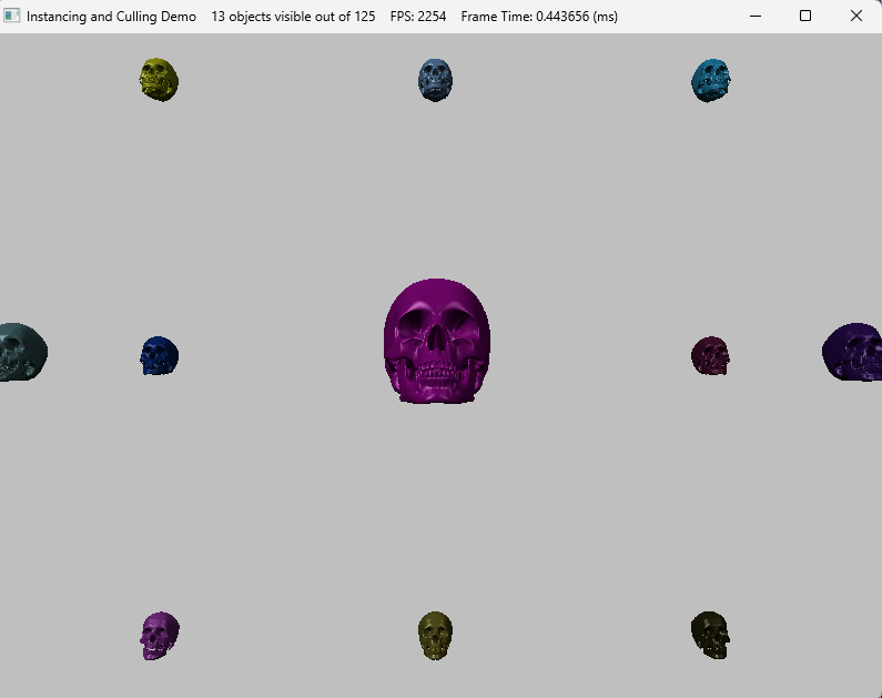
우선 예제코드를 실행시켜보자. 실행화면 위쪽에 보면 125개의 물체 중에 13개만 보이고 있다는 것을 알 수 있다. 여기서 만약 2번을 눌러주면 인스턴싱모드가 꺼지면서 125개가 다 그려지며 프레임이 낮아지는 것을 볼 수 있다. 이때 13개가 보인다는 것은 컬링과 관련이 있다.

이때 같은 물체에서 달라지는 부분은 position과 같은 부분으로 이 연산은 쉐이더 코드의 VS부분의 구조체를 보면 된다. 아래에 변수가 VS단계에 입력으로 들어오는 부분에 인스턴싱관련된 부분이다.
struct VertexIn
{
    float3 PosL     : POSITION;
    float3 NormalL  : NORMAL;
    float2 Tex      : TEXCOORD;
    // 인스턴싱
    row_major float4x4 World  : WORLD;
    float4 Color    : COLOR;
    uint InstanceId : SV_InstanceID;
};
코드 상에서는 Vertex부분에 쉐이더코드에 맞게 묘사해주도록 변수가 맞춰져있다.
typedef struct D3D11_INPUT_ELEMENT_DESC
{
    LPCSTR SemanticName;
    UINT SemanticIndex;
    DXGI_FORMAT Format;
    UINT InputSlot;			//인스턴싱일때 구분해줘야함
    UINT AlignedByteOffset;
    D3D11_INPUT_CLASSIFICATION InputSlotClass;
    UINT InstanceDataStepRate;
} 	D3D11_INPUT_ELEMENT_DESC;

static ComPtr<ID3D11InputLayout> InstancedBasic32;

const D3D11_INPUT_ELEMENT_DESC InputLayoutDesc::InstancedBasic32[8] =
{
	{"POSITION", 0, DXGI_FORMAT_R32G32B32_FLOAT, 0, 0, D3D11_INPUT_PER_VERTEX_DATA, 0},
	{"NORMAL",   0, DXGI_FORMAT_R32G32B32_FLOAT, 0, 12, D3D11_INPUT_PER_VERTEX_DATA, 0},
	{"TEXCOORD", 0, DXGI_FORMAT_R32G32_FLOAT, 0, 24, D3D11_INPUT_PER_VERTEX_DATA, 0},
	{ "WORLD", 0, DXGI_FORMAT_R32G32B32A32_FLOAT, 1, 0, D3D11_INPUT_PER_INSTANCE_DATA, 1 },
	{ "WORLD", 1, DXGI_FORMAT_R32G32B32A32_FLOAT, 1, 16, D3D11_INPUT_PER_INSTANCE_DATA, 1 },
	{ "WORLD", 2, DXGI_FORMAT_R32G32B32A32_FLOAT, 1, 32, D3D11_INPUT_PER_INSTANCE_DATA, 1 },
	{ "WORLD", 3, DXGI_FORMAT_R32G32B32A32_FLOAT, 1, 48, D3D11_INPUT_PER_INSTANCE_DATA, 1 },
	{ "COLOR", 0, DXGI_FORMAT_R32G32B32A32_FLOAT, 1, 64,  D3D11_INPUT_PER_INSTANCE_DATA, 1 }
};
이때 D3D11_INPUT_PER_INSTANCE_DATA 뒤에 나오는 1이라는 수는 instance data step이라는 옵션으로 instance별 자료 원소 하나당 그릴 instance의 개수이다. 이렇게 묘사해준 값을 IA단계에서 넘겨줘야한다. IASetVertexBuffers에서 2번째 매개변수를 2로 설정해주고 있는 것을 볼 수 있다. 이 2는 2가지 값을 넘겨주고 있다는 것인데 이 2가지 값은 SkullVertexBuffer와 InstanceBuffer이다.
이렇게 해준다음 마지막에 DrawIndexedInstanced로 그려주면 된다. 이때 몇개를 그려줄지에 대한 값도 넘겨줘야한다.
ID3D11Buffer* vbs[2] = { _skullVB.Get(), _instancedBuffer.Get() };

_deviceContext->IASetVertexBuffers(0, 2, vbs, stride, offset);
_deviceContext->IASetIndexBuffer(_skullIB.Get(), DXGI_FORMAT_R32_UINT, 0);

_deviceContext->DrawIndexedInstanced(_skullIndexCount, _visibleObjectCount, 0, 0, 0);
이때 InstanceBuffer를 묘사해주는 부분을 가보면 InstanceData를 통해 데이터를 채워주고 이 값에 따라 InstanceBuffer를 채워준다.
void InstancingAndCullingDemo::BuildInstancedBuffer()
{
	const int32 n = 5;
	_instancedData.resize(n * n * n);

	float width = 200.0f;
	float height = 200.0f;
	float depth = 200.0f;

	float x = -0.5f * width;
	float y = -0.5f * height;
	float z = -0.5f * depth;
	float dx = width / (n - 1);
	float dy = height / (n - 1);
	float dz = depth / (n - 1);

	for (int k = 0; k < n; ++k)
	{
		for (int i = 0; i < n; ++i)
		{
			for (int j = 0; j < n; ++j)
			{
				// Position instanced along a 3D grid.
				_instancedData[k * n * n + i * n + j].World = XMFLOAT4X4(
					1.0f, 0.0f, 0.0f, 0.0f,
					0.0f, 1.0f, 0.0f, 0.0f,
					0.0f, 0.0f, 1.0f, 0.0f,
					x + j * dx, y + i * dy, z + k * dz, 1.0f);

				// Random color.
				_instancedData[k * n * n + i * n + j].Color.x = MathHelper::RandF(0.0f, 1.0f);
				_instancedData[k * n * n + i * n + j].Color.y = MathHelper::RandF(0.0f, 1.0f);
				_instancedData[k * n * n + i * n + j].Color.z = MathHelper::RandF(0.0f, 1.0f);
				_instancedData[k * n * n + i * n + j].Color.w = 1.0f;
			}
		}
	}

	D3D11_BUFFER_DESC vbd;
	vbd.Usage = D3D11_USAGE_DYNAMIC;
	vbd.ByteWidth = sizeof(InstancedData) * _instancedData.size();
	vbd.BindFlags = D3D11_BIND_VERTEX_BUFFER;
	vbd.CPUAccessFlags = D3D11_CPU_ACCESS_WRITE;
	vbd.MiscFlags = 0;
	vbd.StructureByteStride = 0;

	HR(_device->CreateBuffer(&vbd, 0, _instancedBuffer.GetAddressOf()));
}
Rasterizer에서 실행되는 것으로 영역에서 벗어난 부분이라면 보이지 않게 하는 데 이 부분에서 컬링이 실행되긴한다.
하지만 그 앞 단계까지에서 그려줄 애들은 이미 계산을 해준 상태이기 때문에 만약 안그려줘도 되는 아이라면 CPU단에서 처리해주는 것이 효율적일 것이다. 이를 해주는 것이 절두체 컬링(Frustum Culling)이다.
아래 코드를 보면 2개의 변수가 각각 해골이 그려져있는 영역과 카메라의 절두체 영역으로 절두체 컬링을 위한 것이다.
//해골 영역
BoundingBox _skullBox;
//절두체 영역
BoundingFrustum _camFrustum;
이를 통해 카메라의 절두체 안에 있는지 체크하고 만약 있다면 그려주는 코드는 UpdateScene에 있다.
void InstancingAndCullingDemo::UpdateScene(float dt)
{
if (_frustumCullingEnabled)
{
	XMVECTOR detView = XMMatrixDeterminant(_camera.View());
	XMMATRIX invView = XMMatrixInverse(&detView, _camera.View());

	D3D11_MAPPED_SUBRESOURCE mappedData;
	_deviceContext->Map(_instancedBuffer.Get(), 0, D3D11_MAP_WRITE_DISCARD, 0, &mappedData);

	InstancedData* dataView = reinterpret_cast<InstancedData*>(mappedData.pData);

	for (uint32 i = 0; i < _instancedData.size(); ++i)
	{
		XMMATRIX W = ::XMLoadFloat4x4(&_instancedData[i].World);
		XMVECTOR D = ::XMMatrixDeterminant(W);
		XMMATRIX invWorld = ::XMMatrixInverse(&D, W);

		// View space to the object's local space.
		XMMATRIX toLocal = ::XMMatrixMultiply(invView, invWorld);

		// Decompose the matrix into its individual parts.
		XMVECTOR scale;
		XMVECTOR rotQuat;
		XMVECTOR translation;
		::XMMatrixDecompose(&scale, &rotQuat, &translation, toLocal);

		// Transform the camera frustum from view space to the object's local space.
		BoundingFrustum localspaceFrustum;

		_camFrustum.Transform(localspaceFrustum, XMVectorGetX(scale), rotQuat, translation);
		//XNA::TransformFrustum(&localspaceFrustum, &_camFrustum, );

		// 그려줘야하는지 체크
		if (localspaceFrustum.Contains(_skullBox))
		{
			// Write the instance data to dynamic VB of the visible objects.
			dataView[_visibleObjectCount++] = _instancedData[i];
		}
	}

	_deviceContext->Unmap(_instancedBuffer.Get(), 0);
}
}
절두체 판단에서는 한면에 대해서 이 물체가 절두체 이전에 있는지 이후에 있는지를 통해 그려주는지 판단해주고 이를 6면에 대해서 해주면 된다. 이 중에 하나라도 통과하지 못하면 그려주지 않는다.
'게임공부 > Directx11(물방울책)' 카테고리의 다른 글
| [Directx11][C++][물방울]12. Cube Mapping (3) | 2024.11.01 |
|---|---|
| [Directx11][C++][물방울]11. Picking (5) | 2024.10.31 |
| [Directx11][C++][물방울]9. Tessellation (5) | 2024.10.29 |
| [Directx11][C++][물방울]8. Compute Shader (1) | 2024.10.22 |
| [Directx11][C++][물방울]7. Geometry Shader (1) | 2024.10.22 |